R = ρL/A
V = IR
This is called Ohm's Law. Recall that the unit of electric potential is the volt, V, the unit of current is the amp, A, and the unit of resistance is the ohm, Ω.
P = I²R = VI = V²/R
Rs = R1 + R2 + R3 + ...
where R1, R2, ..., are the individual resistances of resistors 1, 2, .... Using similar notation, the equivalent resistance of resistors in parallel, Rp, is given by
1/Rp = 1/R1 + 1/R2 + 1/R3 + ...
A 0.01 m long cylindrical germanium resistor (ρ = 2 Ω-m) with radius 0.002 m is placed in a circuit that has a current of 3 A. (a) What is the resistance of the resistor? (b) What is the potential across this resistor? (c) How much power is used by the resistor? (d) How much energy is used if the current runs for 10 seconds? The cross sectional area of a cylindar is given by A = πr², where π is the number pi (3.14) and r is the radius.
R = ρL/A = (2 Ω-m)(0.01 m)/[(3.14)(0.002 m)²] = 1592 Ω
V = IR = (3 A)(1592 Ω) = 4775 V
P = I²R = (3 A)²(1592 Ω) = 14,324 W
E = Pt = (14,324 W)(10 sec) = 143,240 J
A 2 Ω resistor is in parallel with a 5 Ω resistor, and the combination is in series with a 1 Ω resistor. (a) What is the equivalent resistance of the two resistors in parallel? (b) What is the equvalent resistance of the combination of all three resistors?
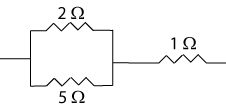
The first step is to draw a picture of the resistors. The next step is to combine resistors that are clearly in series or in parallel. After the initial combinations are formed, the new resistors are combined in the same way and this is continued until there is only one resistor. In this problem that means doing part (a) and then part (b).
For part (a): 1/Rp = 1/R1 + 1/R2
1/Rp = 1/(2 Ω) + 1/(5 Ω) = 7/(10 Ω)
Rp = 10/7 Ω = 1.43 Ω (a)

We can now draw the new 1.43 Ω resistor and the 1 Ω resistor in series and then combine them together.
For part (b): Rs = R1 + R2
Rs = 1.43 Ω + 1 Ω = 2.43 Ω (b)
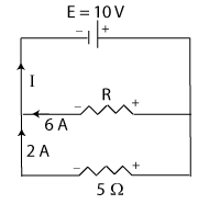
A 10 V battery is in parallel with two resistors as shown. (a) Use the junction rule to find the unknown current I. (b) Use the loop rule two different ways to find the unknown resistance R.
When doing these problems the first step is to draw and label all of the components. The next step is to decide the direction of the currents. This is somewhat arbitrary, but the result of a wrong choice will only be a negative current, which means the current is really going the opposite direction. For this problem it was chosen to have one current going up away from the left junction point, and the other two currents going into the same junction point. There must always be at least one in and one out current at every junction point.
After choosing the direction of the current the next step is to label the charges on the batteries and on the resistors. The batteries will always have the charges such that the positive side is the side with the long line and the negative side is the side with the short line. The charges on the resistors are determined by the direction of the current. The side where the current goes in is positive and the side where the current goes out is negative. Check this out in the diagram for this example.
Once everything is labeled the junction rule and the loop rule can be applied.
For part (a): Total current in = Total current out; 2 A + 6 A = I = 8 A
For part (b): Do the top loop, starting at the left junction point and going clockwise, for the first way.
+10 V - (6 A)(R) = 0; R = (10 V)/(6 A) = 1.667 Ω
For the second way start at the left juction point and go clockwise around the bottom loop.
+(6 A)(R) - (2 A)(5 Ω) = 0; R = (2 A)(5 Ω)/(6 A) = 1.667 Ω
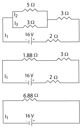
Find the currents I1, I2, and I3 in the top circuit at the right.
To get these currents we need a loop with only one unknown current. So, the first thing is to combine the two resistors in parallel. That results in three resistors in series which can be combined. That will leave one unknown current and a loop rule can be used to determine the current I1.
Remember that we need to label the charges on the resistors and that they are determined by the direction of the current. When there is only one battery, the direction of the current is away from the positive terminal of the battery. That would make the current counterclockwise in this circuit. The positive side of the resistor is the side where the current goes into the resistor. Starting at the right of the battery and going counterclockwise in the bottom circuit, the loop rule would give:
(-6.88 Ω)I1 + 16 V = 0; I1 = (16 V)/(6.88 Ω) = 2.326 A
Go back to the original picture and choose the loop that includes the 2, 3, and 5 Ω resistors to get the current I2.
(-2 Ω)I1 - (3 Ω)I1 - (5 Ω)I2 + 16 V= 0
I2 = [16 V - (2 Ω)I1 - (3 Ω)I1]/(5 Ω) = 0.874 A
Now use the loop that includes the 2, 3, and 3 Ω resistors to get the current I3.
(-2 Ω)I1 - (3 Ω)I1 - (3 Ω)I2 + 16 V= 0
I3 = [16 V - (2 Ω)I1 - (3 Ω)I1]/(3 Ω) = 1.46 A
I3 could also have been determined using the junction rule or the small loop at the top.
I2 + I3 = I1; I3 = 2.33 A - 0.87 A = 1.46 A
-(5 Ω)I2 + (3 Ω)I3 = 0; I3 = (5/3)(0.874 A) = 1.46 A
The major component of an electrical meter is the galvanometer. A galvanometer is a sensitive current detecting device that has a relatively high resistance, e.g. 100 Ω, with a full scale deflection when a small amount of current, e.g. 2 mA, goes through it.
To make an ammeter, which detects current, a shunt is connected in parallel with the galvanometer and the whole device is put in series with the circuit. Most of the current goes through the shunt, but a small amount goes through the galvanometer which will have more deflection with more current. The meter must be made so that the maximum deflection is related to the amount of current going through the shunt.
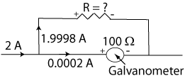
For example, use a galvanometer with 100 Ω of resistance and a maximum current for full deflection of 2 x 10⁻⁴ A. To build an ammeter with a maximum deflection corresponding to 2 A, we can use a loop rule to calculate the resistance needed in the shunt. Start at the junction point going into the ammeter, go up through the shunt and back around the loop through the gavanometer to the original junction point.
-(1.9998 A)R + (2 x 10⁻⁴ A)(100 Ω) = 0
R = [(2 x 10⁻⁴ A)(100 Ω)]/(1.9998 A) = 0.01 Ω
The resistance of the shunt would need to be 0.01 Ω in order for full deflection of the galvanometer to correspond to 2 A. When less than 2 A was in the circuit, the needle deflection would be less. The deflection can be calibrated to measure between zero and two amps. To make a zero to 10 A meter, the resistance of the shunt would need to be 0.002 Ω.
To make a voltmeter a multiplier is placed in series with the galvanometer and this combination is placed in parallel with the circuit that is being measured. The multiplier has a large resistance so that only the current needed to deflect the galvanometer goes along this path. Most of the current goes through the circuit.
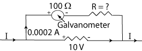
Using the same galvanometer as before (100 Ω and 2 x 10⁻⁴ A) the multiplier for a 2 V voltmeter could be determined using a loop rule that starts where the current goes in, goes up through the galvanometer and multiplier, and then goes back around through the voltage that is being measured.
-(2 x 10⁻⁴ A)(100 Ω) - (2 x 10⁻⁴ A)R + 2V = 0
R = [2 V - (2 x 10⁻⁴ A)(100 Ω)]/(2 x 10-4 A)] = 9,900 Ω
The shunt for a 2 V meter with this galvanometer would have to be 9,900 Ω. For a voltage of less than 2 V, the needle would not deflect as far and again the deflection can be calibrated to read any voltage between zero and 2 V. A voltmeter that could read up to 10 V would need a shunt of 99,900 Ω.